Saturday, July 20, 2013

MAC Address Structure


Here’s where we get into how Ethernet addressing works. It uses the Media Access Control (MAC) address burned into each and every Ethernet network interface card (NIC). The MAC, or hardware, address is a 48-bit (6-byte) address written in a hexadecimal format. You can see your system's MAC address by typing following command at command prompt:
C\>ipconfig /all

Structur of MAc address 
MAC address is divided in to two parts. The organizationally unique identifier (OUI) is assigned by the IEEE to an organization. It’s composed of 24 bits, or 3 bytes. The organization, in turn, assigns a globally administered address (24 bits, or 3 bytes) that is unique to each and every adapter it manufactures.
dixitmicroit.blogspot.com
Structure of MAC
The high-order bit is the Individual/Group (I/G) bit. It can be either 0 or 1.
0 means that the address is the MAC address of a device (unicast).
1 means that the address represents either a broadcast or multicast address.

The next bit is the global/local bit, or just G/L bit.
0, this bit represents a globally unique address (as by the IEEE). When the bit is a 1, it represents a locally unique address. but i know you are confuse, actually 0 means this address belong to physical NIC.
1 means this address this may to virtual NIC if you are running virtual machine on physical machine.

The low-order 24 bits of an Ethernet address represent a manufacturer-assigned code. This portion commonly starts with 24 0s for the first card made and continues in order until there are 24 1s for the last (2^24 = 16,777,216th) card made.

For example 02-00-4C-4F-4F-50
02-00-4c assigned by IEEE for gigabyte manufacture so all gigabyte adapter have same 24 bit but next(4f-4f-50) 24 bit is assigned and start by gigabyte.

02-00-4c-00-00-01  first MAC address
02-00-4c-ff-ff-ff  last MAC address

Ethernet Technology

Ethernet was first implemented by a group called DIX (Digital, Intel, and Xerox). They created and implemented the first Ethernet LAN specification. This was a 10Mbps network that ran on coax. When designing your LAN, it’s really important to understand the different types of Ethernet media available to you.

Here are the original IEEE 802.3 standards:
10Base2
Known as thinnet and can support up to 30 workstations on a single segment. Uses a physical and logical bus with BNC connectors and thin coaxial cable. The 10 means 10Mbps, Base means baseband technology (digital signaling), and the 2 means almost 200 meters. 10Base2 Ethernet cards use BNC (British Naval Connector, Bayonet Neill Concelman, or Bayonet Nut Connector), T-connectors, and terminators to connect to a network.

10Base5 10Mbps, baseband technology, up to 500 meters in length using thick coaxial cable. Known as thicknet. Uses a physical and logical bus with AUI connectors. Up to 2,500 meters with repeaters and 1,024 users for all segments.

10BaseT 10Mbps using category 3 unshielded twisted pair (UTP) wiring for runs up to 100 meters. Unlike with the 10Base2 and 10Base5 networks, each device must connect into a hub or switch, and you can have only one host per segment or wire. Uses an RJ45 connector (8-pin) with a physical star topology and a logical bus.

Here are the expanded IEEE Ethernet 802.3 standards, starting with Fast Ethernet:
100Base-TX
most commonly known as Fast Ethernet, uses EIA/TIA category 5, 5E, or 6 UTP two-pair wiring.
One user per segment; up to 100 meters long. It uses an RJ45 connector with a physical star topology and a logical bus.

100Base-FX Uses fiber cabling 62.5/125-micron multimode fiber. Point-to-point topology; up to 412 meters long. It uses ST and SC connectors, which are media-interface connectors.

1000Base-CX Copper twisted-pair that can run only up to 25 meters and uses a special 9-pin connector known as the High Speed Serial Data Connector (HSSDC).

1000Base-T Category 5, four-pair UTP wiring up to 100 meters long and up to 1Gbps.

1000Base-LX Single-mode fiber that uses a 9-micron core and 1300 nm laser and can go from 3 kilometers up to 10 kilometers.

10GBase-T 10GBase-T is a standard provide 10Gbps connections over conventional UTP cables (category 5e, 6, or 7 cables). 10GBase-T allows the conventional RJ45 used for Ethernet LANs.

10GBase-Extended Range (ER) An implementation of 10 Gigabit Ethernet running over single-mode fiber. It uses extra-long-wavelength lasers at 1,550 nm. It has the longest transmission distances possible of the 10-Gigabit technologies: anywhere from 2 meters up to 40 km, depending on the size and quality of the fiber used.

10GBase-Short Wavelength (SW) 10GBase-SW is a mode of 10GBase-S for MMF with an 850 nm laser transceiver with a bandwidth of 10Gbps. It can support up to 300 meters of cable length. This media type is designed to connect to SONET equipment.

Ethernet Cabling

Ethernet Cabling
A discussion about Ethernet cabling is an important one. You need to really understand the following three types of cables:
A-Straight-through cable.
B-Crossover cable.
C-Rolled cable
We will look at each in the following sections.

1-Straight-Through Cable
The straight-through cable is used to connect the following devices:
A-Host to switch or hub
B-Router to switch or hub
Four wires are used in straight-through cable to connect Ethernet devices
Notice that only pins 1, 2, 3, and 6 are used. Just connect 1 to 1, 2 to 2, 3 to 3, and 6 to 6.

dixitmicroit.blogspot.com
Straight Cable
B-Crossover Cable
The crossover cable can be used to connect the following devices:
A-Hub to hub
B-Host to host
C-Hub to switch
D-Router to host
E-Switch to switch
F-Router to Router via Fast Ethernet ports

The same four wires used in the straight-through cable are used in this cable; we just connect different pins together Notice that here we connect pins 1 to 3 and 2 to 6 on each side of the cable.

dixitmicroit.blogspot.com
Crossover cable

C-Rolled Cable
You can use a rolled Ethernet cable to connect a host EIA-TIA 232 interface to a router console serial communication (COM) port. If you have a Cisco router or switch, you would use this cable to connect your PC running HyperTerminal to the access router console. Eight wires are used in this cable to connect serial devices, but not all eight are used to send information.

Cisco Hierarchical Model

The Cisco Three-Layer Hierarchical Model
hierarchy that helps us understand where things belong, how things fit together, and what functions go where.
Hierarchy has many of the same benefits in network design when used properly, it makes networks more predictable. It helps us define which areas should perform certain functions like as which router should be placed where, where we should apply access list, etc.

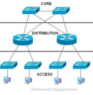
The Cisco hierarchical model can help you design, implement, and maintain a scalable, reliable hierarchical internetwork. Cisco defines three layers of hierarchy.
The following are the three layers (figure 1.0) and their typical functions:
The core layer: backbone
The distribution layer: routing
The access layer: switching

dixitmicroit.blogspot.com
Figure 1.0
Each layer has specific responsibilities.
1-Core Layer:
The core layer is responsible for transporting large amounts of traffic both reliably and quickly. The responsibility of core layer is to switch traffic as fast as possible. If there is a failure in the core, every single user can be affected.
Things to not do:
A-Don’t do anything to slow down traffic. like as access lists, intervlan routing, and packet filtering.
B-Avoid expanding the core (adding devices) when the internetwork grows its performance may be affected.
Things to do:
A-Design the core for high reliability. redundancy, such as Gigabit Ethernet (backup links)
B-Design with speed in mind. The core should have very little latency.
C-Select routing protocols with lower convergence times.

The Distribution Layer:
The distribution layer is also called workgroup layer and is the communication point between the access layer and the core. The primary functions of the distribution layer are to provide routing, filtering, and WAN access.
Actions that generally should be done at the distribution layer:
A-Implementing security (access lists) and network policies, NAT and firewalls.
B-Redistributing between routing protocols, including static routing.
C-Routing between VLANs.
D-Defining broadcast and multicast domains.

The Access Layer
The access layer controls user and workgroup access to internetwork resources. The access layer is sometimes referred to as the desktop layer.
The following are some of the functions of access layer:
A-Use of access control and policies
B-Creation of separate collision domains (segmentation)
C-Workgroup connectivity into the distribution layer
D-Technologies such as Gigabit or Fast Ethernet switching are often used with this layer.

Active Directory Partitions

The configuration data of active directory database is sored in ntds.dit file, that is replicated to every domain controller in the forest. NTDS.DIT organizes data in three different partitions or also known as naming context.

1- Domain Partition
It contains all objects information such as users, groups, computers and even group policy containers.

2- Schema Partition
It stores information about schema that is object classes and attributes for example user, group, these are classes and their property tabs options like as full name, email, address are attributes.

3- Configuration Partition
It stores the logical structure of the forest means how they are interconnected  and also sites subnet and services information.

Additionally their are two more partitions used by Active Directory 
A- Application is one more partition supported by ADDS. it store a portion of data that contains the objects that is required by an application or service. (ex- dns) this partition is only  replicated when there is need and only for required domain controller.

B- Global Catalog : GC is a partition that stores information about every objects in the forest, it does not contain all attribute of every objects, instead it contains subset of attributes that is helpfull for searching the object in the forest hence is called partial attribute set (PAS).

Configure DHCP Server in Server 2008

Configure DHCP Server in Windows

(DYNAMIC HOST CONFIGURATION PROTOCOL)
DHCP is a protocol in the TCP/IP suite of protocols. A computer running DHCP service is called DHCP server.DHCP is used to give ip addresses to the computers automatically. It also gives other networking details like default gateway address, DNS server address and WINS server address to the computers automatically. A client PC can obtain ip address automatically using DHCP server.
DHCP is useful in large networks as it help in ip address management. It is also helpful in remote connectivity of computers by allocating ip address automatically to the clients.

The process of obtaining ip address by the client from the DHCP server is called ROSA process.
SOME TERMS
Static Address: - It is the address given to a computer manually by the user.

Dynamic Address: - It is the address obtained by the client automatically from the DHCP server.

Scope: - It is the range of addresses defined for distribution to the clients in the network.

Super scope: - It is a group of scopes and may contain multiple scopes.

Lease Duration: - It is the period for which a client can keep or use the ip address obtained from the DHCP server. When lease time finishes, the client again request for the ip.

Reservation: - In a DHCP server, an ip address can be reserved for a client so that the client always gets the same address from the DHCP. This is called Reservation.


HOW TO INSTALL DHCP?
Go to server manager and select add roles then select DHCP then follow steps and install it


HOW TO CONFIGURE DHCP SERVER?
  1. Open all programs>   administrative tools > DHCP.

  2. Right-click IPv4 > new scope. (as shown in figure).

  1. Click next. Give a name to the scope and click next.

  2. Define range for the addresses and click next.
  1. Give addresses which you don't want to give to clients if necessary, and click next.

  2. Click next > Select Yes > next.

  3. Give address of router if necessary and click next.

  4. In the parent domain, type DNS domain name and in the server name, type name of your DNS server. Click on resolve and click next.

  5. Type WINS server address if necessary and click next.

  6.  Click next > finish and activate it.
    Now you have successfully configured you DHCP Server. 

    Go to the client computers and open TCP/IP properties: Select 'obtain an ip address automatically' and also Select 'obtain a DNS server address automatically'. Click O.K. > Close.
Ofter some time check obtained ip address from cmd by using ipconfig /all command

Some usefull Commands
You can use the following commands to troubleshoot ip address assignment on a client PC. These commands must be given in the MS-DOS mode:
Ipconfig /release
This command is used to release the ip from the client and set the ip to 0.0.0.0.

Ipconfig /renew
This command is used to obtain ip address again from the DHCP server and to renew the ip address.
APIPA address
APIPA stands for Automatic Private IP address Assignment. If a client is not able to obtain ip from the DHCP server, it assigns ip automatically to itself in the range: 169.254.0.0. - 169.254.255.255
Above rage of addresses are private addresses and are called APIPA addresses.

RESERVATION
If you want assign a specific ip address for particular system you can do this by reservation but you need to know about MAC address of that system.

1. Open DHCP management and create a scope.

2. Click on the scope and right-click on 'Reservations' > New Reservation.

3. In the Reservation Name, type any name.

4. Type the ip address which you want to reserve for a client PC.

5. Also type MAC address of that client PC.

6. Click on Add and then click on Close.

SUPERSCOPE
Super scope is a group of scopes and can be used to create logical sub networks or subnets within a single physical network. It also helps in making administration of many scopes easier. The process of creating logical sub networks in a single physical network is called Multi-netting. You can also use super scope if a single scope is providing insufficient addresses.

For example, in a company, there are 500 PCs. The company policy is to use only Class C addresses with default subnet mask. But a given Class C address range can have only 254 addresses .In such a situation ,we create two scopes having Class C address range with different Network IDs.The scopes will generate 254+254 = 508 addresses for our clients.
The two scopes will be put in a super scope and we will have two logical sub networks in a single physical network.
DHCP RELAY AGENT
DHCP Relay Agent is a protocol which help in passing DHCP broadcast messages made by the clients, through the router, so that clients in the subnets which don't have DHCP server can obtain ip address from the DHCP server present in the other subnet(sub network).

Configure NAT in Linux


NAT stand for Network address translation that allows you to use private ip address to access public network , because NAT translate private ip address in to public ip address. This also ensure your network security from hackers by hiding your actual IP information..
dixitmicro.blogspot.com
Simple NAT LAN Setup

Use the following rule to implement NAT for the internal network to update iptable.
# iptables -t nat -I POSTROUTING -o eth0 -s 10.8.8.0/24 -j MASQUERADE
(-t means table, -o means output interface, -s means source address. I am using classless ip).
Then restart iptable servcie by using following commands.
# service iptables restart
# service iptables save

Make the following change to the kernel: to forward LAN routing.
# echo 1 > /proc/sys/net/ipv4/ip_forward
OR use persistent
#vi /etc/sysctl.conf
net.ipv4.ip_forward = 1
Where 0 means LAN routing is disabled.
Now go to Private client end and configure ip address and try to open any public site it should be open.

VLAN Configuration


A VLAN is a switched network that is logically segmented by function, project team, or application, without regard to the physical locations of the users. Any switch module port can belong to a VLAN, all  packets are forwarded and flooded only to end stations in the VLAN.

Range of VLANs
Normal-range VLANs are VLANs with VLAN IDs 1 to 1005. You can  add, modify or remove configurations for VLANs 2 to 1001 in the VLAN database. (VLAN IDs 1 and 1002 to 1005 are automatically created and cannot be removed.)
VLAN also breaks the collision doamin to increase network performance.

You can set these parameters when you create a new normal-range VLAN

•VLAN ID
•VLAN name
•VLAN type (Ethernet, Fiber Distributed Data Interface [FDDI],

Configure VLAN on Switch 1 
 First of all create VLANs that you needed then attach ports with  appropriate VLANs. 
Here is a sample how to create VLAN on Cisco switch. In example i have created two VLANs named as mkt (id 3) and sales (id 2).
Use #show vlan  to verify vlan configuration on privilege mode.
Now systems that are associated with same VLAN name and ID  will be able to communicate with each other, in above example  sales1 and mkt1 will not be able to communicate to each other due to different VLANs.

Configure ACL in Linux

ACL is extended set of permissions on files and directories that give advanced security when needed. For example you can set different permission for different user on a single file or directory. Two commands control ACLs: getfacl and setfacl. When you use the ls -l or ll command, a plus sign (+) on the side of the permission indicates ACL permission.

Step 1.  Before you can even use ACLs, however, you need to make sure that the file system has been mounted with the ACL parameter:
# mount | grep acl
Because nothing is returned, you know that all currently mounted file systems do not have ACLs set up to be used. To mount the file system with the ACL option use the following command:
# mount –t ext4 -o acl,remount /dev/sda5 /data

Step 2. If your file system isn’t already mounted, you could also use the following:
# mount –t ext4 -o acl /dev/sda5 /data

Step 3. To verify, you can use the previous command:
# mount | grep acl
/dev/sda5 on /data type ext4 (rw,acl)

Step 4. Add the following line in your /etc/fstab file:
#vim /etc/fstab
/dev/sda5 /data ext4 defaults,acl 1 2
Save and close the file.

Step 5. To make the changes take effect, you need to remount the file system:
# mount -o remount /data

Step 6. You can now verify that your file system has the ACL option:
# mount | grep -i acl
/dev/sda5 on /data type ext3 (rw,acl)

Exercise: Create a file and apply ACL for it
Step 1. Create a sample file on which you can test an ACL in the /data/backup directory:
# cd /data/backup
#touch file1
To Show default permission type following command.
# getfacl /data/backup/file1

Step 2. Set the ACL on that file so user1 also has access to this file: For example i want to assign full permission on /data/backup/file1 to user1
# setfacl -m u:user1:rwx /data/backup/file1

Step 3.
Now check the ACL permissions:
# getfacl /data/backup/file1
# file: file1
# owner: root
# group: root
user: rw-
user:user1:rwx
group :r--
mask: rwx
other: r--
Now login as user1 and it should be able to modify file1.
Step 4. Use the setfacl command to remove the ACL for user1:
# setfacl -x u:user1 /data/backup/file1

Step 5. Verify that the ACL has been removed:
# getfacl /data/backup/file1
# file: file1
# owner: root
# group: root
user: rw-
group: r--
mask: r--
other: r--
Now login as user1 and try to modify it should not be able to modify file1.

Step 6. If you have multiple ACLs set up on a single file, you can remove them all with the -b option
# setfacl -b filename

Grub Configuration File

GRUB has only a single config file, /boot/grub/grub.conf actually have soft links with /etc/grub.conf. When GRUB starts, it reads its configuration from the main config file. You can make changes on the command line to test different features of GRUB.
Now let’s look at the new version of the grub.conf file for RHEL6:
# cat grub.conf
default=0
timeout=5
splashimage=(hd0,0)/grub/splash.xpm.gz
hiddenmenu
title Red Hat Enterprise Linux (2.6.32-71.el6.x86_64)
root (hd0,0)
kernel /vmlinuz-2.6.32-71.el6.x86_64 ro root=/dev/mapper/vg_rhel01-lv_root
rd_LVM_LV=vg_rhel01/lv_root rd_LVM_LV=vg_rhel01/lv_swap rd_NO_LUKS rd_NO_MD
rd_NO_DM LANG=en_US.UTF-8 SYSFONT=latarcyrheb-sun16 KEYBOARDTYPE=pc
KEYTABLE=us crashkernel=auto rhgb quiet
initrd /initramfs-2.6.32-71.el6.x86_64.img

Now let's have a look the meaning of these options
default=0 means default kernel will load that is Linux, 1 means i want to load other OS or kernel if  installed
timeout=5 means you have 5 sec. to select manual options. if you want to modify kernel before booting you need to interrupt booting within 5 seconds.
splashimage= location of file that will use during booting.
title= display name of Kernel or O.S.
root(hd0,0)= where is boot partition is located in my case partition 0 on disk 0.
kernel = used kernel parameters like as encryption, RAID, LVM, language etc. Don't change any grub options until you don't know exact meaning of that otherwise you might be unable to boot system if you misconfigure any option.
Now use any file editor to modify options and reboot your system to see results. If there is any problem write to us on comment box we will try to help you.

Network Setting in RHEL6

In this blog we will look, how to configure network setup to allow system to communicate to each other.
Networking is an important factor because without it, you would not be able to communicate with your network, or share files with your users.
When you’re working with network interfaces, there are two files you need to know:
/etc/sysconfig/network :This file contains gateway and hostname information.
/etc/sysconfig/network-scripts :This directory contains all the interface config files for your system.

Let’s start by looking at the hostname and networking information:
# cat /etc/sysconfig/network
NETWORKING=yes
NETWORKING_IPV6=yes
HOSTNAME=RHEL01
The first two lines tell the system whether or not to enable networking for IPv4 and IPv6. By default, they are both enabled. The third option defines the system hostname. Each network interface has its own config file in this directory that follows the format ifcfg-ethX, where X is the number of the network card. For example,
# cat /etc/sysconfig/network-scripts/ifcfg-eth0
DEVICE=eth0
BOOTPROTO=dhcp
HWADDR=08:00:27:30:74:AA
ONBOOT=yes
DHCP_HOSTNAME=RHEL01
TYPE=Ethernet

DEVICE=              interface you are working with.
BOOTPROTO=    protocol in use in my case it is DHCP.
HWADDR=          MAC address of device.
ONBOOT=           interface is enable during booting.
TYPE=                  you are using Ethernet technology.

You can launch system-config-network-tui utillity to change ip address if required.
Or you can also use following command to assign static ip address.
# ifconfig eth0 172.168.1.1 netmask 255.255.255.0

To bring the interface down, use ifdown:
# ifdown eth0

To bring the interface up use ifup:
# ifup eth0

To view the current IP address of the eth0 interface, use the following command:
# ifconfig eth0

When you made any changes with your adapter do'nt forget to restart the network service:
# service network restart

Additional network commands
ping command Tests the connectivity between two hosts
example #ping -c 2 192.168.1.1

traceroute command Looks for step by step path from host to host
example #traceroute 192.168.1.1

netstat command Shows information about connections (open, closed, and listening)
exmaple #netstat -tuape |grep sshd
tcp 0 0 *:ssh *:* LISTEN root 8627 2674/sshd
If nothing is returned, there is chance that the service isn't running or listening.

route command Shows routing information
#route

When you really need to see the details of what is going you can use a packet capture utility to view data being sent across the interfaces on your machine. you can use the tcpdump utility.
# tcpdump –i eth0 –w capturefile
-i means interface
-w means write in to file (capture file is the name of file)

To review the information you've captured, call the tcpdump program again:
# tcpdump –r capturefile | less
-r means read from file

VIM editor

Many times users may need to edit a file, so there are many files editor that you can use to edit files like as nano, vi, vim, emacs, gvim, gedit etc. Vim stands for "Vi IMproved". Vim is a text editor which includes almost all the commands from vi editor and few more. Apart from the vim command, the vim packages may also provide gvim, the Gnome version of vim. vim can operate in two modes: command mode and insert mode.
The editor always starts in command mode. it is used to copy, move, replace, delete, and perform some other functions. These are some popular vi commands:

Moving commands
 h   to move the cursor to the left
 l   to move it to the right
 k   to move up
 j   to move down

Save and exit commands
:w      will save (write) the file.
:q!     forces the exit without saving.
:wq    will save and exit.
:wq!   overrides read-only permission.

Copy and paste commands
dd    will delete a lines.
dw    will delete a word.
x      will delete the character on which the cursor is positioned.
yy    will copy a whole line.
p      will paste copied data.

Search commands
/search  will perform the search any word you will put, replace serach with word that you want to search.
:num      replace num with number to go for particular line.

Insert mode is used to insert text in the file. To go insert mode press i and you will see insert message on bottom side, if you want to come back in command mode just press ESC key.
 a will append a new line.
 i will insert text on current cursor position.
 o will insert a blank line under the current cursor position.

For more information there is a built-in tool called vimtutor that can be used learn a lot, just type
#vimtutor

Understanding Runlevel

Runlevels:
When the system boots up, it queries for the default runlevel, which is defined in the /etc/inittab file. When that default runlevel is decided, the system boots into that particular runlevel. The different runlevels are essentially “states,” which allow services to be started or stopped depending on the runlevel you are using. There are total six runlevels which are shown in the /etc/inittab file.

0 Halt essentially the system is power off
1 Single-user mode is used to enter single-user mode, which you can use to perform maintenance like as reset the root user’s password.
2 Multiuser with partial services without networking.
3 Full multiuser with networking (text mode)
4 Not used
5 Full multiuser graphical mode (provides a GUI desktop login)
6 Reboot

Runlevel Utilities
Let’s now look at the many system utilities that help you manage the system in different runlevels.
1- shutdown     Brings the system to a powered-off state or can reboot the system
2- halt         Powers down the system
3- reboot       Reboots the system
4- poweroff     Works the same as the halt command
5- chkconfig    Manages what runlevels services start and stop at
6- runlevel     Displays the current and previous runlevels
7- init         Changes runlevels
8- ntsysv       Works similarly to chkconfig in that it is a menu-driven service management utility

Let's look some examples:
# shutdown -h now
 complete power off,
# shutdown -r now
reboot the system
# shutdown -h 120
As a final example, delay the shutdown by 2 minutes:

You can also change the current runlevel you’re in by using the init command.
Step 1. Check the runlevel you’re in:
# runlevel
N 5
According to output you can see you are working on runlevel 5.
As an alternative, you can also use the who command to produce the same results:
# who -r
run-level 5 2010-09-05 09:45 last=S
Step 2. Because you are in runlevel 5, change over to runlevel 3:
# init 3
Now you will switch from runlevel 5 to runlevel 3.

Breaking root Password in RHEL6

Some time you may need to recover your root password if you forget this, it is very simple to break root
password in linux. use the following steps to break root password.

Breaking root password:
1- reboot your system.
2- When system ask to select OS press any key to interrupt default OS selection.
3- press ‘e’ to edit kernel parameter before booting.
4- Choose the second option ‘Kernel/vmlinuz-2.6.i8, again press ‘e’.
5- Type ‘1’ at the lend of the line to go in single user mode.
6- Then press ESC key to return back and then press ‘b’ to boot system.
7- Now system will reboot and start with single user mode prompt.
8- Here type sh3.2# passwd -d root  then press enter this will remove password for root user.
10-Now reboot your system and you will be able to login without password where you can change password for root.
But people says that linux is highly secure but how when anyone can break password as so easy.
Oh dear linux is really secure but you need to do some security configuration. In next section we will learn how to protect grub from being modify. Now if you will try to break root password you need to know grub password.

Grub Security (set password on grub after installation):
1-Open terminal and type following command to generate md5 encrypted password
# grub-md5-crypt
Password:
Confirm password:
(Here you will see encrypted code, copy this carefully no any extra character like as space).
2-Now edit grub.conf file with any editor.
# vim /boot/grub/grub.conf
Here you will see a lot of option go to under "hiddenmenu" and type following syntax
Password --md5 paste encrypted password that you have copied
3-Save this file.
4-Reboot your system and try to modify grub to break root password, it will prompt for grub password.
Now your root password is protected.

Configure RAID in RHEL6

Redundant Array of Inexpensive Disk:
RAID Disk partitions technology that allow more advanced features such as redundancy and better performance. This technology is usually used on server based storage where a large amount of storage required with fault tolerance. Before we describe how to implement RAID, let’s look at the different types of RAID Levels: There are many types of RAID Levels but right now i am going to describe only those that are required for RHCE exam preparation:

A- RAID 0 (Striping): disks are grouped together to form one large drive. This offers better performance at the cost of availability. If any single disk in the RAID fail, the entire set of disks becomes unusable. It require minimum two disks. For eaxample suppose you have two disks wtih 50GB in size, you can combine both to treat as a single disk to achieve 100Gb space.

B- RAID 1 (Mirroring): disks are copied from one to another, allowing for redundancy. If one disk fail, the other disk takes over, having an exact copy of data from the original disk but here is slow write speed. Two disk minimum.

C- RAID 5 (Striping with parity): disks are similar to RAID 0 and are join together to form one large drive. The difference here is that 25% of the disk is used for a parity bit, which allows the disks to be recovered if a single disk fail. RAID 5 require minimum three disks.
While RAID can be implemented at the hardware level, the Red Hat exams are not hardware based and therefore focus on the software implementation of RAID. Next, let’s use the three free disk drives (hdb, hdc, and hdd) to set up a RAID array.

Step 1. Install the following package:
# yum install -y mdadm

Step 2. Verify the install:
# rpm -qa | grep mdadm
mdadm-3.1.3-1.el6.x86_64
Now we are going to start with a RAID 5 setup, so you need to make partitions on at least three different disks. You can use the mdadm command to create any RAID array.
Syntax: mdadm [options]

Options:
-a  Adds a disk into a current array.
-C --create Creates a new RAID array.
-D --detail Prints the details of an array.
-f   Fails a disk in the array.
-l --level Specifies level (type) of RAID array to create.
-n --raid-devices Specifies the devices in the RAID array.
-S --stop Stops an array.
-v --verbose Provides verbose output.

Step 3. You can use the following command to create a new RAID array (/dev/md0), which is a RAID 5, and it contains three disks:
# mdadm -Cv /dev/md0 —level=5 -n3 /dev/sda6 /dev/sda7 /dev/sda8
mdadm: Defaulting to version 1.2 metadata
mdadm: array /dev/md0 started.

Step 4. Use the mdadm command again to verify that the RAID array has been created successfully:
# mdadm –D /dev/md0
/dev/md0:
Version : 1.2
Creation Time : Thu jul 27 14:09:23 2013
Raid Level : raid5
Array Size : 16769024 (15.99 GiB 17.17 GB)
Used Dev Size : 8384512 (8.00 GiB 8.59 GB)
Raid Devices : 3
Total Devices : 3

Step 5. View the status of the newly created RAID array:
# cat /proc/mdstat

What to Do When a Disk Fails:
Suppose that a disk in the array failed. In that case, you need to remove that disk from the array and replace it with a working one.

Step 1. To fail a disk in the array, use this command:
# mdadm /dev/md0 -f /dev/sda6
mdadm: set /dev/sda6 faulty in /dev/md0
Step 2. Verify that the disk in the array has failed by looking at the details of the RAID array:
# mdadm -D /dev/md0
Number Major Minor RaidDevice State
0 8 17 0 active sync /dev/sda7
1 8 33 1 active sync /dev/sda8
2 0 0 2 removed
3 8 49 - faulty spare
/dev/sda6

Now that you know that the disk has failed, you need to remove it from the array so it can be replaced.
Step 3. To remove a disk from the array, use this command:
# mdadm /dev/md0 -r /dev/sda6
mdadm: hot removed /dev/sda6 from /dev/md0

Step 4. Look at the last few lines of the RAID details again:
# mdadm -D /dev/md0
/dev/md0:
Number Major Minor RaidDevice State
0 8 17 0 active sync /dev/sda7
1 8 33 1 active sync /dev/sda8
2 0 0 2 removed
You can see from the last line of the output that the disk has been “removed.”

Step 5. When the disk is partitioned, you can add it back to the array as follows:
# mdadm /dev/md0 -a /dev/sda6
mdadm: re-added /dev/sda6
Step 6. Verify that it has been added properly:
# mdadm -D /dev/md0
/dev/md0:
Number Major Minor RaidDevice State
0 8 17 0 active sync /dev/sda7
1 8 33 1 active sync /dev/sda8
3 8 49 2 spare rebuilding /dev/sda6
Note: Notice that the state of the drive is “rebuilding" it may take approx 2 minute to rebuid please wait and verify again.

Deleting a RAID Array
:
Now that you have successfully implemented a RAID array, you can take it apart by deleting the array.
Step 1. To delete an array, first stop it:
# mdadm -vS /dev/md0
mdadm: stopped /dev/md0
Step 2. Then remove the RAID array device:
# mdadm --remove /dev/md0

Configure Quota in Linux

Quota is a feature that allow you to set specific limit for specific user or group on particular disk partition. There are two types of limits A-soft limit: when user exceed their soft limit a warning appear but user is allowed to store data. B-Hard limit when exceed hard limit user is not allowed to store data beyond this limit.
For a working example, you can configure quotas on the /companydata file system so that you can limit the amount of data that users can store in this directory.

Follow these steps to apply quota.
You need to install the required packages before you can use quotas on your system.
To install the quota package, use the following:
# yum install – y quota

Verify that the package is installed successfully:
# rpm -qa | grep quota
quota-3.17-10.el6.x86_64

Although Red Hat supports quotas in the kernel by default but you can verify quota support from the kernel with the following command:
# grep -i config_quota /boot/config-`uname -r`
CONFIG_QUOTA=y
CONFIG_QUOTACTL=y
y means that the kernel support quotas.
After verifying that the package is installed and that the kernel does support quotas, you can start configuring Quota.

To start setting up quotas, let’s look at some of the commands:
quotaon    Turns on quota tracking
quotaoff   Turns off quota tracking
edquota    Edits the settings of a user’s quota
quota       Allows each user to see his disk consumption
repquota   Generates a report of quota usage
quotacheck Initializes a quota database

Configure quota
You first need to edit the /etc/fstab file to specify which file systems you want to utilize quotas. You can
apply quota limit for users, groups, or both.

Step 1. In the /etc/fstab file, edit the following line:
For example if i want to apply quota on /dev/sda5 partition which is mounted on /companydata and filesystem uses as ext4.

#vim /etc/fstab
/dev/sda5 /companydata ext4 defaults,usrquota,grpquota 1 2
Save and close the file.

Step 2. You now need to remount the /companydata file system before the changes take effect.
# mount -o remount /companydata

There are two files that maintain quotas for users and groups:
aquota.users User quota file
aquota.group Group quota file

To start the quota system, you use the quotacheck command.
Syntax: quotacheck [options] <partition>
-c Don’t read existing quota files
-u Checks user quotas
-g Checks group quotas
-m Doesn’t remount the file system as read-only

Step 3. Create the quota files:
# quotacheck -ugm /companydata/

Step 4. Verify that the quota files were created successfully:
# ls /companydata/
aquota.group aquota.user lost+found

Step 5. Run the command manually the first time just to make sure that quotas are turned on:
# quotaon -v /companydata/

Step 6. Now set the limit with edquota command
Syntax: edquota [-u | -g] [username | groupname]
Change the line for the /dev/sda5 file system to look like the following:
# edquota -u kamal
Disk quotas for user kamal (uid 502):
Filesystem     blocks   soft    hard   inodes soft hard
/dev/sda5       0       2000   2500   0       0   0
(where 2000 is soft limit and 2500 is hard limit in KB)
Save your changes and close the file.

Step 7. Login as kamal user and create some files and directories, Use the repquota command to verify uses quota limit.
# repquota -uv /companydata/

Manage Services in Linux

Service Management
On any system it is important to manage the running services. Managing services enables you to stop, start, restart services whenever needed. In Linux, services can also be called daemons that's why most of the services end with a "d" such as sshd, httpd, dhcpd, vsftpd etc.

TO manage services at each runlevel, you can use the chkconfig command.
Syntax: chkconfig [option] service_name.
Options that you can use:

--list [name] Shows the status of the service at each runlevel.
--level <levels> Enables or disables the service at the given levels.
 <service_name>  <on|off|

Step 1. To check the status of the sshd service use following command:
# chkconfig --list sshd
sshd 0:off 1:off 2:on 3:on 4:on 5:on 6:off
According to output you can understand the sshd service will be started at runlevels 2, 3, 4, and 5. It will be stopped at runlevels 0, 1, and 6.

Step 2. Use the off option to disable the service at boot.:
# chkconfig sshd off

Step 4. Re-enable the SSH service:
# chkconfig sshd on
Aside from using the chkconfig command, you can do the same task by using the ntsysv command.
#ntsysv
And you will see a menu-driven window where you can manage services.

You can also use the service command. You can use this to start, stop, and query the status of services.
Step 1. Usually, it is a good idea to always check the status of the service first:
# service ntpd status
ntpd is stopped

Step 2. When you know that the service is stopped, you can start it:
# service ntpd start
Starting ntpd: [ OK ]

Step 3. Stop the NTP service:
# service ntpd stop
Shutting down ntpd: [ OK ]

Step4. To restart the sshd service
# service sshd restart